AS 1101.3 Welding Symbols
AS 1101.3 is the Australian Standard for welding symbols. It provides a standardized system for indicating the type of weld, its size and location, and any other necessary information for welding on engineering drawings.
The standard includes guidelines for the use of symbols on drawings and the placement of those symbols in relation to the components being welded.
It is designed to be used in conjunction with other relevant standards, such as AS 1100 Technical drawing and AS 1554.1 Structural steel welding.
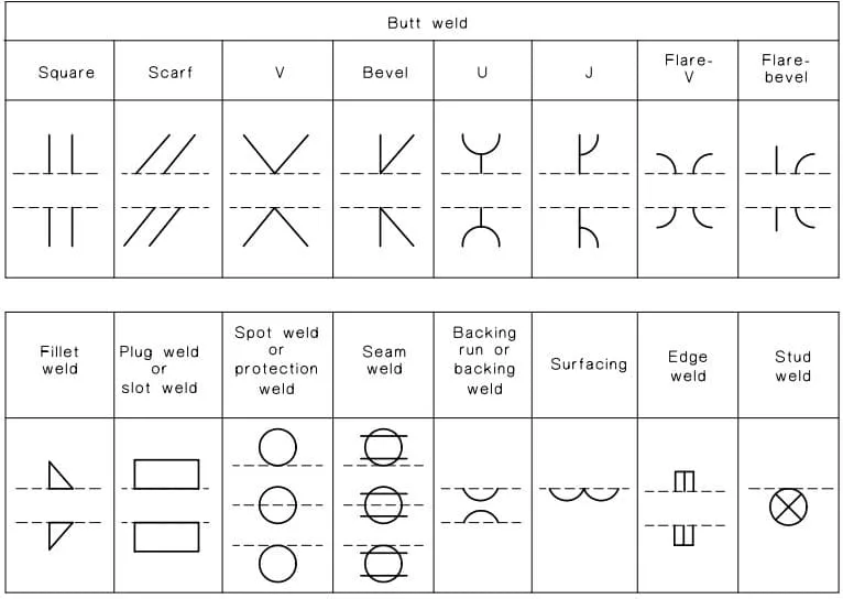
AS 1101.3 Australian Standard basic welding symbols
AS 1101.3 provides a standardized system of symbols for indicating the type of weld, its size and location, and any other necessary information for welding on engineering drawings.
The basic welding symbols used in AS 1101.3 include:
- Square Butt Weld,
- Scarf Butt Weld,
- V Butt Weld,
- Bevel Butt Weld,
- U Butt Weld,
- J Butt Weld,
- Flare-V Butt Weld,
- Flare bevel Butt Weld,
- Fillet Weld,
- Plug or Slot Weld,
- Spot weld or projection weld,
- Seam Weld,
- Backing run or Backing weld,
- Surfacing,
- Edge Weld,
- Stud Weld.

These are the basic welding symbols used in AS 1101.3 standard, but the standard provides more detailed information and additional symbols for different types of welding and fabrication.
Parts of a Welding Symbol as per AS 1101.3
The basic parts of a welding symbol used in AS 1101.3 include:
- Weld symbol: A symbol placed on reference line with an arrow pointing to the joint that is to be welded.
- Type of weld: Indicated by symbols located on or near the reference line.
- Size of weld: Indicated by a number or a letter located on left side of weld symbol placed on the reference line. For example, the size of a fillet weld can be indicated by a number, such as “6”, which represents 6mm.
- Length of weld: Indicated by a number located on or near the reference line. This number represents the length of the weld in millimeters.
- Pitch of weld: Indicated by a number located on right side of weld symbol. This number represents the distance in millimeters between the center of one weld and the center of the next weld.
- Contour and preparation of the parts to be welded: E.g., G for grind, M for machine, F for flush weld.
AS 1101.3 Arrow side and other side weld symbol
In AS 1101.3, the arrow side of a welding symbol indicates the side of the joint that the welder should carry out the welding.
The arrow points towards the side of the joint that the weld shall be placed. If the weld symbol is placed below the reference line, welding shall be carried out at the arrow side direction.
The other side of the weld symbol is meant when it is placed on the top of the reference line as shown in the below example.

AS 1101.3 Supplementary welding symbols
AS 1101.3 provides additional or supplementary welding symbols that can be used in conjunction with the basic welding symbols to indicate specific information about the weld. These supplementary welding symbols include:
- Weld all around,
- Site weld,
- Complete penetration from one side,
- Backing or spacer material,
- Contour symbols (Flush, convex or concave).

Groove Weld Symbol example as per AS 1101.3
Below is an example of Double U groove according to the AS 1101.3 standard. The welding symbol include weld penetration depth, included angle and root gap.

Flare Groove weld symbols as per AS1101.3
Flare groove welds are often used in structural steel fabrication, such as in the construction of buildings, bridges and other structures.
A flare groove weld is a type of groove weld that is used to join two pieces of metal at a flared joint where atleast one joining member is having radius.
The most common flare groove weld symbols according to the AS 1101.3 are shown below:

AS 1101.3 Intermittent and zig-zag fillet weld symbol
Intermittent fillet welds and zig-zag fillet welds are types of fillet welds that are used in certain situations where a continuous fillet weld is not practical or possible.
An intermittent fillet weld is a fillet weld that is made in short segments, with gaps between the segments. The segments are typically spaced out to allow for access to the joint or to provide room for movement or expansion.
Intermittent fillet welds are used in situations where a continuous weld would be difficult to make or would interfere with other components of the structure.
A zig-zag fillet weld is a fillet weld that is made in a zig-zag pattern along the joint, rather than in a straight line. The zig-zag pattern allows for better distribution of the weld metal along the joint and can be used to provide additional strength to the weld.
Both of these types of fillet welds are used when a continuous fillet weld would be impractical or difficult to make.
They are typically used in situations where a fillet weld is needed but the structure does not allow for continuous welds or the structure needs to be disassembled or make accessible.
Welding symbols for intermittent and zig-zag fillet welds are shown below.

AS 1101.3 Surfacing weld symbol
AS 1101.3 provides a symbol for surfacing welds, which are also known as cladding or overlay welds.
A surfacing weld is a type of weld that is used to apply a layer of material onto the surface of a base metal.
The purpose of a surfacing weld is to improve the surface properties of the base metal, such as corrosion resistance, wear resistance, or to repair a surface that has been damaged.
The symbol for a surfacing weld consists of a reference line, an arrow pointing to the side of the joint (where the surfacing is to be applied) and half-circle surfacing weld symbol placed on the reference line.

Material Welding is run by highly experienced welding engineers, welding trainers & ASNT NDT Level III bloggers.
We strive to provide most accurate and practical knowledge in welding, metallurgy, NDT and Engineering domains.


