There are different standards of welding symbols, and each one has its own applications. Apart from AWS A2.4, the 2nd most common welding symbol standard is the ISO 2553 (or BS EN 22553) for ISO weld symbol (used in UK, EU and Asia). Other notable welding symbols standard is AS 1101.3.
ISO 2553 weld symbols are similar to AWS A2.4 and the only difference is the placement of welding symbols for the arrow side & other side if system “A” for welding symbols is used.
System “B” is similar to AWS A2.4 weld symbol placement and reference line significance.
ISO weld symbol Part
An ISO Weld symbol consists of 5 main parts:
- An Arrow Line
- A reference line (System A or B)
- A dotted (dashed) line parallel with a solid reference line (System A)
- An elementary and supplementary Weld Symbol
- Weld dimensions/ sizes
- Tail (Optional part)- V-shaped part of the welding symbol

ISO 2553 welding symbols
In ISO and BS Welding symbols standards, the term Weld Symbol and Welding Symbol are used interchangeably while in AWS A2.4, these terms are having a different meanings.
ISO Weld symbols are applicable for welding joints, soldered and brazed joints.
In ISO 2553 Standard, welding symbols are divided into three types:
- Elementary Welding Symbols
- Supplementary Welding symbols
- Complementary welding symbols
ISO 2553 Elementary welding symbols
Elementary welding symbols are placed on the reference line to show the weld type and weld joint preparation. Weld size is placed on the left side of the elementary symbol.
The basic ISO 2553 elementary welding symbols are given below.

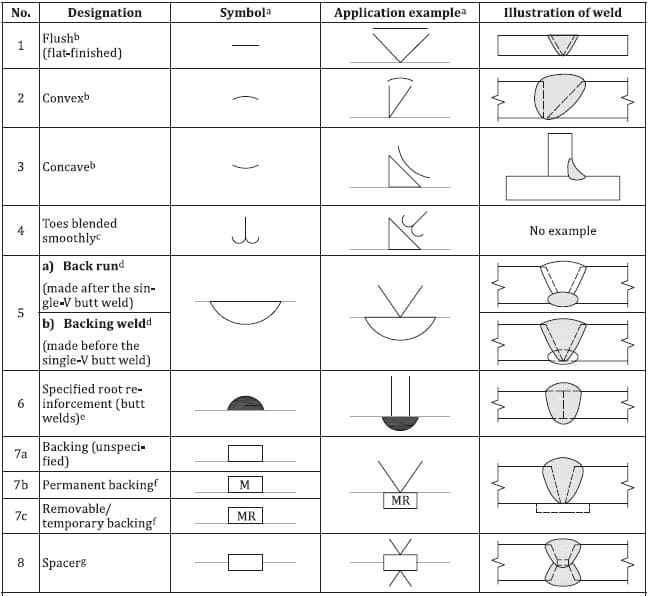
ISO 2553 Supplementary welding symbols
Supplementary symbols are used in conjunction with the elementary symbol to provide additional data related to the welding joint. For example- the type of weld finish or contour.
The main Supplementary Welding symbols (ISO weld symbols) are given below:
Complementary welding symbols
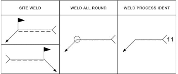
Complementary symbols are used to provide non-symbolic information related to welding. This information can be placed in the tail section or along with a supplementary symbol.
Examples of Complementary welding symbols as per ISO BS 2553 are given below:
- Field or Site Weld
- All around Weld
- Information related to the welding process using the tail section
ISO Welding Symbols terms for weld Sizes
In ISO 2553, short forms for indicating welding sizes are used. A2.4. These shortcodes represent the different sizes of the welds as listed below:
- a: Refer to the fillet weld throat size.
- z: Fillet weld leg size, if used
- s: Refer to groove weld throat size
- M: for Permanent weld backing strip
- MR: for removable weld backing strip
- l: weld length
- e: Weld pitch in intermittent/ stitch weld/ Plug Weld/ Slot Weld/ spot welds
- n: number of welds
- c: width of plug/ slot/ seam weld
- d: diameter of plug/ spot weld
Remember, ISO 2553 uses a metric system of measurement and hence welding dimensions are specified in millimeters and not in inches like AWS
Arrow side and other side welding symbol as per ISO 2553
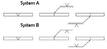
In ISO 2553: 2019 edition, the standard is updated to include two systems for placing the welding symbol (ISO weld symbol) with respect to the reference line.
- System A: Same as the old system, the reference line is made with an additional dotted line.
- System B: Harmonized according to the AWS A2.4
Arrow Side or Other side: System A
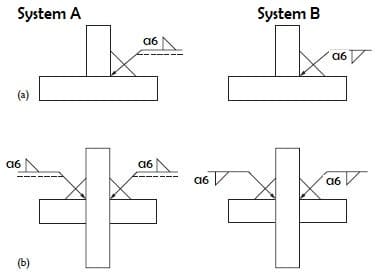
As per system A, the weld symbol placed on the solid reference line means welds are to be made on the arrow side and the welding symbol placed on the dotted line, refers to the weld made on the opposite side of the arrow line.
Arrow Side or Other side: System B
As per system B- there is no dotted reference line, weld symbol placed below the reference line means welds are to be made on the arrow side and the welding symbol placed above the reference line, refers to the weld made on the opposite side of arrow line (similar to AWS A2.4).
ISO fillet Weld symbol
ISO Fillet weld symbols for System A and System B are shown in the below figure.
In system A, the weld symbol for the arrow side is placed on the solid reference line and for other side, it is placed on the dashed line.
In system B, for the arrow side, the fillet weld symbol is placed below the reference line and for other side above the reference line.

Kumar Sandeep
Dr. Sandeep Kumar is a distinguished Welding & Quality Assurance Expert. He holds a Ph.D. in Welding and is a certified International Welding Engineer (IWE) and Technologist (IWT). On the inspection side, he is a Certified Welding Inspector (AWS-CWI) and International Welding Inspection Personnel (IWIP-C), complemented by his ASNT NDT Level III status. Dr. Kumar integrates advanced engineering principles with practical inspection standards to ensure structural integrity and compliance.

